Pachinko Card Reader Emulator System
Connection to Electronic Style Coin Acceptor
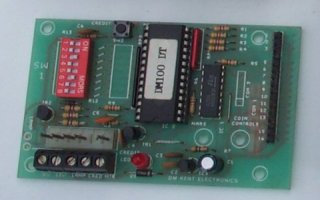
Before connection of an electronic coin/token acceptor, it must be stressed that the Card Reader Emulator unit is not designed to supply power to any external circuits. Any current taken from the +5v DC pin on the expansion connector must be limited to 20mA or below. Failure to observe this limit may result in overheating or permanent damage to both the Card Reader Emulator and the pachinko machine.
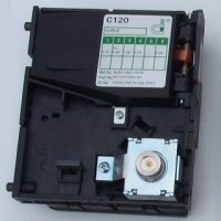
An electronic coin acceptor can be connected to the Card Reader Emulator unit either directly (usually for a single denomination coin acceptor), or via a 'Credit Board'. A credit board is usually used with a multiple denomination coin acceptor and will pulse the single coin output a different number of times, depending on the value of the coin inserted.


In both cases the connection to the Card Reader Emulator's External switch input should be electrically isolated from the coin acceptor/credit board. This can be acheived by using an opto isolator circuit. If this is not done then any static charges or leakage currents between the pachinko machine's power supply and the power supply to the coin acceptor, will pass through the coin acceptors and Card Reader Emulator units, potentially causing permanent damage to both units.
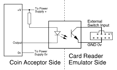
The opto isolator circuit is shown below. A 'transistor output' opto-isolator should be used, these typically come in 4 and 6 pin dual in-line packages (DIP), with the LED connections on one row of pins and the opto-transistor connections on the second row of pins.

The opto-transistor side of the opto isolator should be connected to the external switch input connections of the Card Reader Emulator unit. The Collector pin on the opto-isolator should be connected to the External Switch Input (pin 5) on the expansion connector of the Card Reader Emulator, and the Emitter pin of the opto-isolator to the GND Ov connection (pin 6) on the expansion connector.
The coin acceptor is connected to the LED side of the opto isolator. The output pin of the coin acceptor is connected to the Cathode pin of the LED, and the Anode pin of the LED is connected via a resistor to the positive power supply connection of the coin acceptor.
The value of the resistor is dependant on the power supply voltage required by the coin acceptor.
| Power Supply Voltage | Resistor Value |
| +5v DC | 180 Ohms |
| +12v DC | 680 Ohms |
| +24v DC | 1500 (1k5) Ohms |
If you have any doubt about the correct way to power and connect a coin acceptor to the Card Reader Emulator unit, then please contact us first. As there are so many different styles of electronic coin acceptors available on the worldwide market, we will need to know the make and model number of the acceptor you intend to use, and would appreciate a link to the manufacturers website where specifications and datasheets can be obtained.
For a small charge we can assemble custom connector harnesses to enable coin acceptors to be safely connected to the Card Reader Emulator unit. Please contact us with details of the coin acceptor you intend to use and the harness length required and we will provide an individual quotation.


